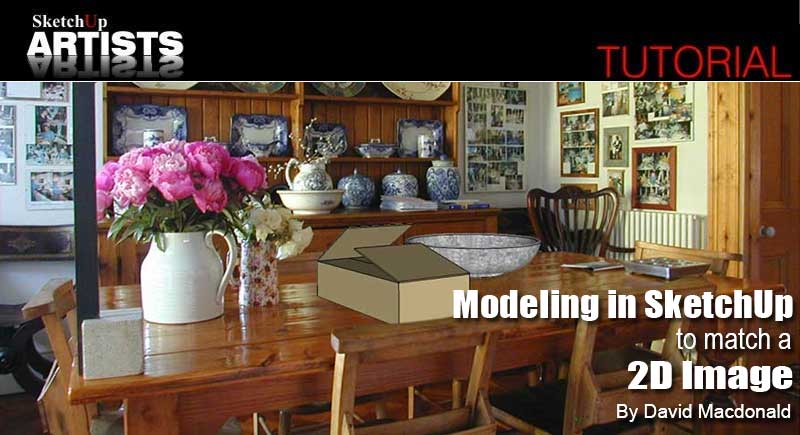
Modeling in SketchUp to Match a 2D Image

By David Macdonald
This is the second of three tutorials concerning the exporting of SketchUp models to other applications as 2D graphics.You should complete each tutorial before moving on to the next as each builds on its predecessor. However each tutorial is complete in itself in as much as you can stop at the end of any of them having acquired a new technique that is complete in itself, without being obliged to finish the series.
Tutorial 1 dealt with the export process, particularly the creation of Alpha masks for your model.
This tutorial deals with the Match Photo dialogue and the creation of a model to insert in a 2D image. Although, as is so often the case with tutorials, the instructions look long and complicated there is nothing in any of the tutorials which requires more than a modest knowledge of SketchUp or Photoshop.
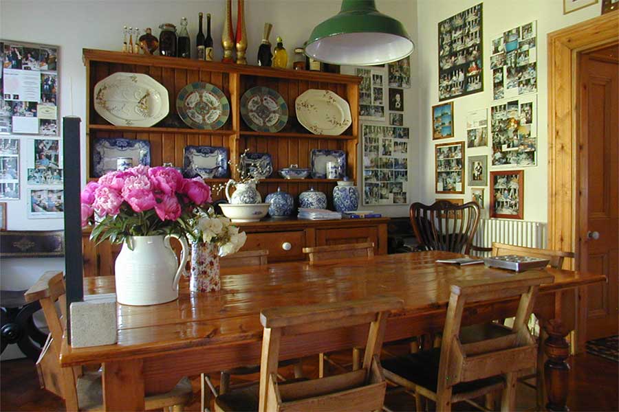
Before we start we are going to need a picture to match for our model. You can get it from here http://img130.imageshack.us/img130/1696/tabled.jpg. Right click the image and choose a save option.
We are going start with this photograph and model a couple of extra items, then export them in 2D with the correct size and perspective to place on the table top.
In a future tutorial I shall take this a stage further and show you how to help make them really belong there with close to photo realism.
IMPORTING THE PICTURE WITH MATCH PHOTO
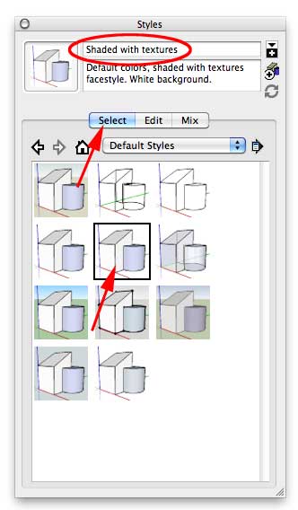
Step 1. First get the picture into SketchUp so that we can create a camera to match it’s perspective. Create a new empty file in SketchUp. We will be drawing by eye only so you can use any template you like as far as units and scale are concerned. However, for exporting, you need a white background and it is easier to follow the tutorial if your drawing matches the screen shots. So open the Styles dialogue box, Window > Styles. Click on the button Select. Select Default Styles in the drop down listing and pick the style Shaded with textures.
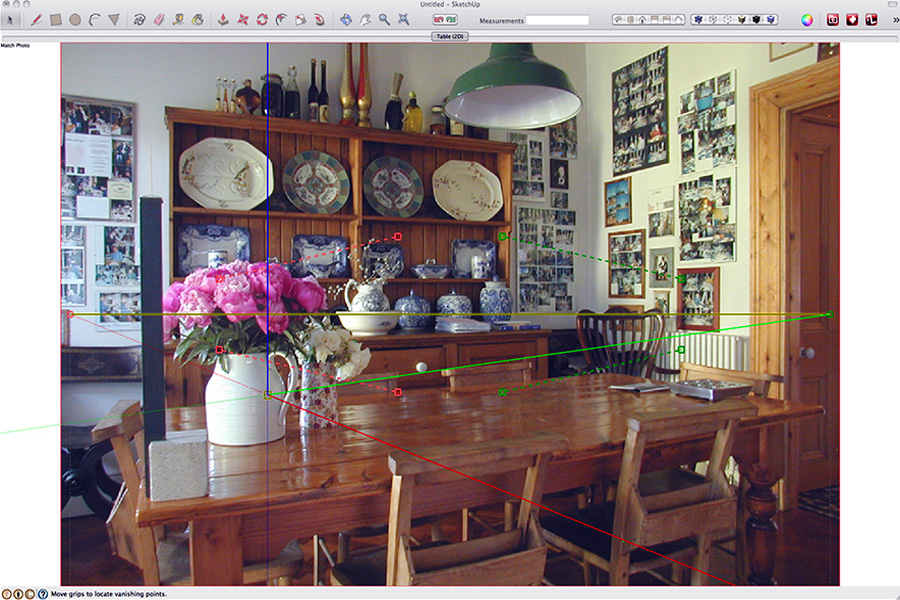
Step 2. Now to load our picture for matching. Window > Match Photo. The Match Photo dialogue will open with everything grayed and unavailable except for the + button in a little circle top left. Click on this to open the File Open dialogue and navigate to the table image you downloaded and open it. Depending on your individual screen shape and layout, your modeling window will look something like this. Regardless of the size and shape of the photograph or your modeling window Match Photo will set the photograph as large as possible with one dimension completely filling the modeling window.
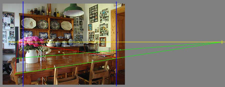
Match Photo can be used either to create a camera for modeling within the context of a 2D picture or can be used to match a pre-existing model to fit a 2D image. If you are an architect or interior designer who wants a model to fit a site photograph or an existing interior then I really recommend you do investigate this great tool. For the next few paragraphs I am going to be talking about vanishing points and other aspects of classical perspective as well as 3D, but nothing harder than school art class. Basically Match Photo determines a 2D image’s vanishing points and from these derives a horizon, which in a photograph is always the height of the lens, a camera position and field of view angle. In the case of this model we want to create some extra items to place on the table top. If the table is perfectly parallel to the walls of the room then it and the room will share the same vanishing points. However, whilst this would appear to be case by simply looking at the picture, there is no reason to suppose that this is necessarily the case. So to be sure I shall derive my perspective and camera position from the table itself and ignore the room. This photo is a classic twin vanishing point perspective with, to all practical intents and purposes, parallel verticals. (I quite deliberately kept the camera at more less the center height of the image without tilting up or down). If we extended the parallel edges of the table to their vanishing points we establish a horizon at roughly half way up the picture, in this case my lens height (The horizon is always at eye level no matter whether you are lying flat on a beach or are on top of one of Dubai’s new ‘super towers’).
Let’s look at the Match Photo dialogue and how we use to it perform the same analysis. Here it is once again in its default opening configuration.
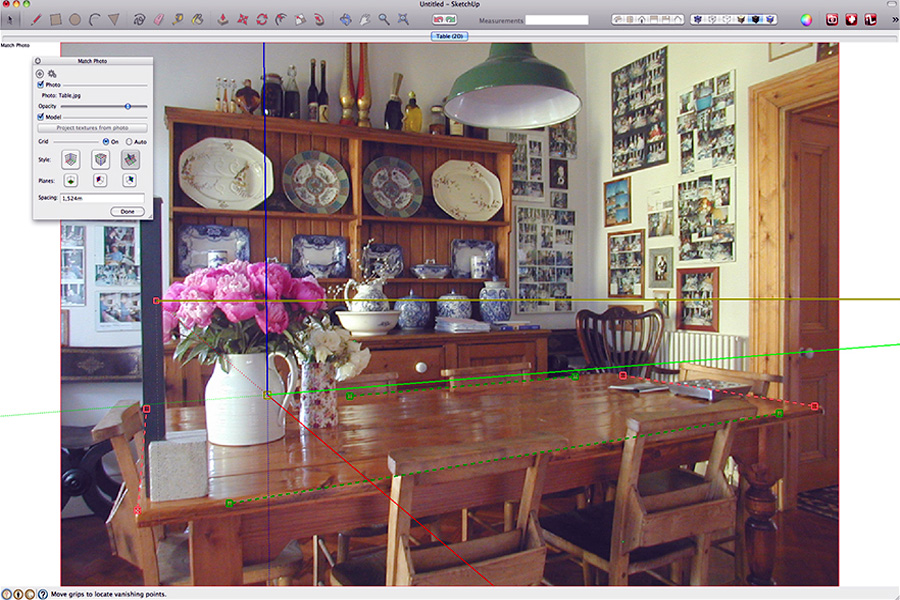
Step 3. In the dialogue there are buttons which display different kinds of grids to help in analysis. In this case the image is so simple they are more of a distraction than an aid so, if any of the bottom row of buttons are gray, click on them to turn their grids off. There several controls in the modeling window to play with. A yellow Horizon Line with handles at each end. Two pairs of red and green Perspective Bars – chain lines with handles on each end for defining parallels, and the Origin – three solid colored axes converging on a yellow handle. Grasping a handle moves the end of a line changing its length and angle as you do so. Grasping the middle of a line moves the whole line. One of the things you will notice is that, as soon as you move one control, the others move too. They are interrelated. The main clue is the coloring of the controls. The two green Perspective Bars are used to set the green axis and the two red Perspective Bars are used to set the red axis, although changing one affects the other as well to some degree. So, in this image, use the red Perspective Bars to define the left and right ends of the table and the green Perspective Bars to define the back and front edges. Here is my setting. I haven’t touched the Origin yet at all (This coloring of the Perspective Bars relative to axis is important. If you suddenly find that the main axis indicator is rotating into silly positions or is even upside down, then you are almost certainly trying to set them to an axis that doesn’t match them).
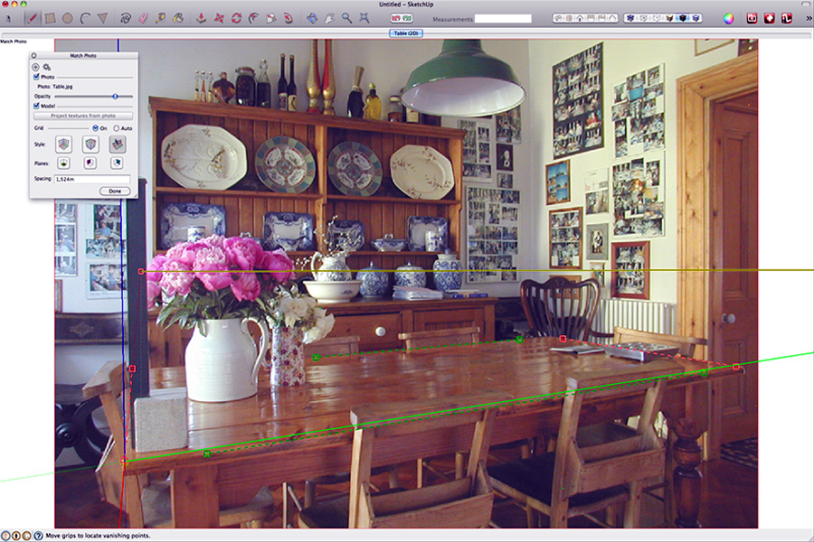
Step 4. Now look back at our earlier analysis of the image’s vanishing points and the horizon they determined. Look familiar? You can see how Match Photo is using the convergence of parallels to determine horizon (camera lens height) and vanishing points, just as my classical 2D construction did. Before we are done with Match Photo there is one more very important option it offers that we have not yet set. So far it has mapped the 3D space of our photograph. Now it is going to let us choose the origin for modeling. This what the Origin is for. Grab the yellow handle and move it around. You will see immediately how the axes move in accordance with the 2D vanishing points. This tool is one tool that does not affect the others’ settings – it is set by them. In this instance we are going to model onto the table top and it was the table top we used as our point of reference to define the 3D space, so pull the yellow handle of the Origin over the near left corner of the table.
We are ready to go. Click Done in the Match Photo Window and close it. Sketchup will save the camera location as a Scene using the Photograph’s filename as the scene name. If you are unfamiliar with Scenes they are essentially a way SketchUp uses of recording a camera position. (They do a lot more besides – but that is all you need to know for this tutorial) Probably a good idea to save your file here. Save it as TableTop.skp
MODELING IN THE CONTEXT OF A MATCHED PHOTO
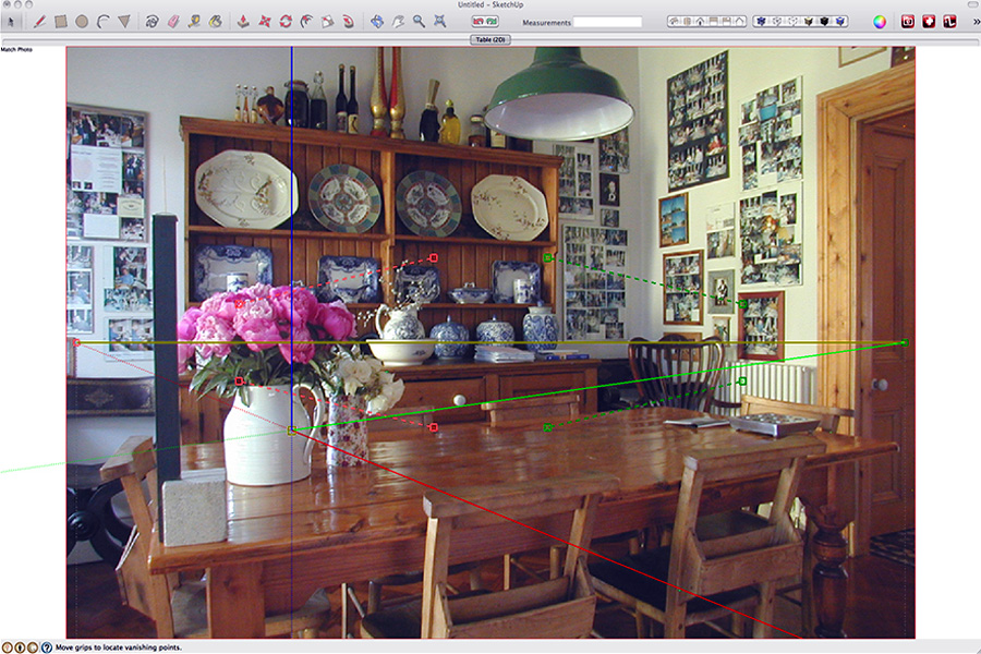
Before we start modeling we need to take a quick look at how SketchUp treats a matched photo modeling window. Use the Orbit tool to change the view of your modeling window. The photo disappears immediately because we have moved the camera on which it was based, but we can still model in the window and move our view around as in any normal SketchUp window. Now click the Table (2D) Scene button at the top of the window. The view and axes are reset to the matched view and the photograph reappears. Now without touching the Orbit control use the Pan and Zoom tools only to navigate.
Orbit Tool
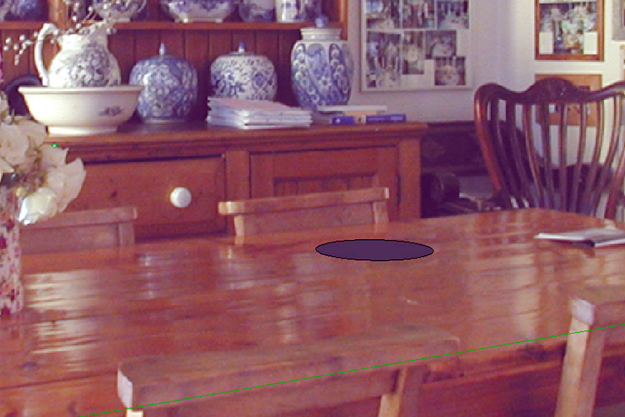
Step 5. In this mode SketchUp treats the image as 2D. We can move in and out and move around within the modeling window without changing the camera position relative to it. This is incredibly useful when we want to adjust detailed modeling within the context of the background photo. We are ready to start modeling. This not a tutorial on modeling so we will stick to basics. We shall model entirely freehand without using measurements. (Although measurements are not needed, try to nonetheless stay close to the the screenshots.) I shall assume that you are familiar with basic SketchUp modeling techniques and give only basic instructions without too much elaboration. What is important here is not modeling as such, but modeling within a context. Select the Circle tool and draw a circle as shown here. See how the circle is drawn on the plane of the table top.
Step 6. Select the whole circle and try moving it around with the Move tool sticking to the red and green axes only. See how it moves perfectly in the context of surface of the table? Put it back in the position shown in the screenshot. We are going to use it as the basis to lathe a bowl. Zoom in onto the circle. Don’t worry about whether you stay in matched view or not. For the next part of the modeling we don’t need to stay in context. In fact we will be obliged to use other camera views. Use the Select tool to select the circle’s outline only. Open the Entity Info window. Window > Entity Info. Change the number of segments to 48. This will give a much smoother circle. This is important when you are going to export into a photo. SketchUp’s default, slightly polygonal, circles can quickly look out of place in a photographic context.
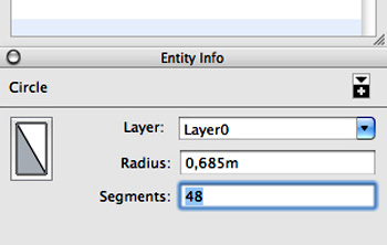
Step 6
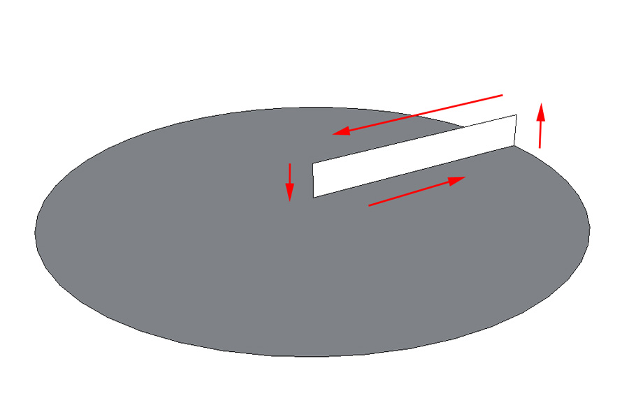
Step 7. Select the Line tool and from the centre of the circle draw a line on the green axis to touch the circumference. Now draw a very short vertical line on the blue axis, another line back to the centre on the green axis and a final vertical to complete a rectangle. Follow the axes carefully to make sure you are staying on them and drawing a proper planar rectangle.
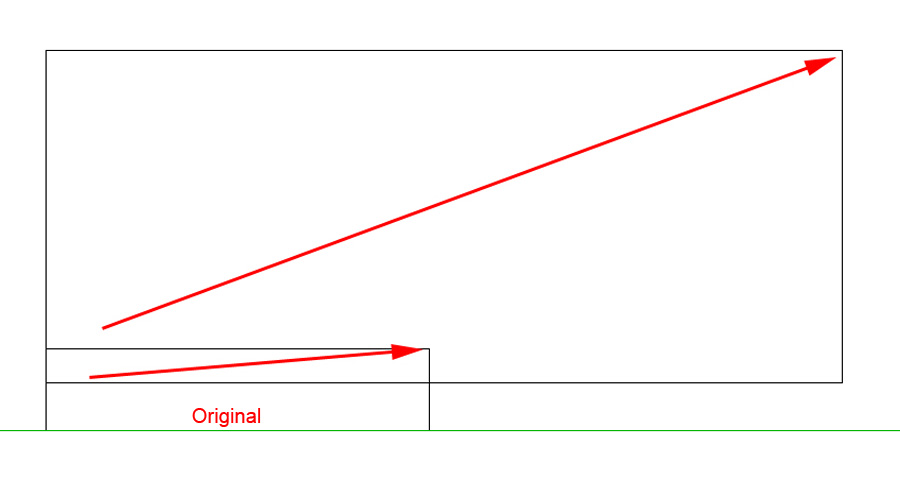
Step 8. Switch to Camera > Standard Views > Right and Camera > Parallel Projection. Starting from the top left corner of the rectangle you just drew, use the the Rectangle tool to draw two more rectangles above the original as shown here.
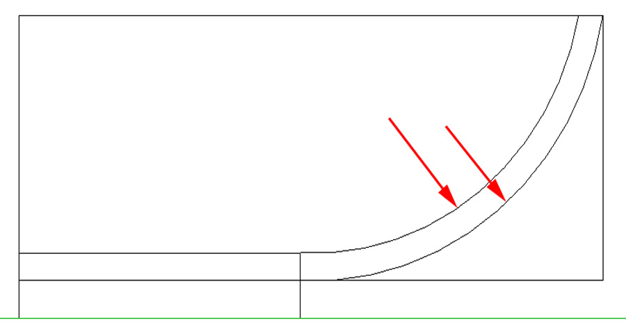
Step 9. With the Arc tool add two roughly parallel arcs emanating from the small rectangle to the top corner and edge of the large rectangle.
Step 10. Once again with the Arc tool join the tops of the two previous arcs with a half circle arc.
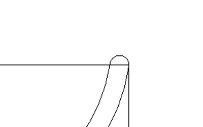
Step 10
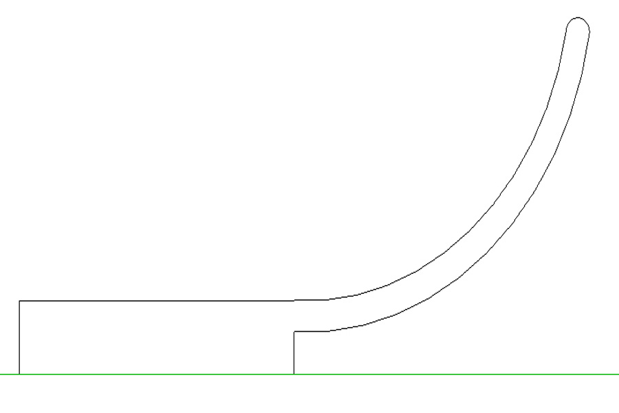
Step 11. Use the Eraser to remove all but the lines shown below.
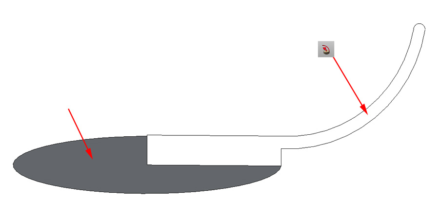
Step 12. We are going lathe this profile into a bowl. Using the Orbit tool tilt the image slightly towards you so you can see the surface of the circle.
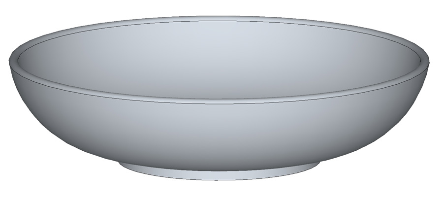
Step 13. With the Select tool select just the surface of the circle. Switch to the the Follow Me tool and click anywhere on the profile that we created. SketchUp will lathe this into a bowl. Depending on the speed of your machine this may take a few moments.
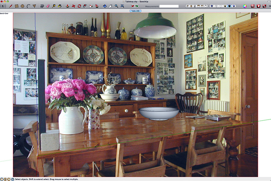
Step 14. Marquee select the entire bowl and Edit > Make Group. Now comes the fun bit …… click on the Table (2D) Scene button in the top of the modeling window. Hey Presto …. SketchUp has placed the bowl right where it belongs on the table!
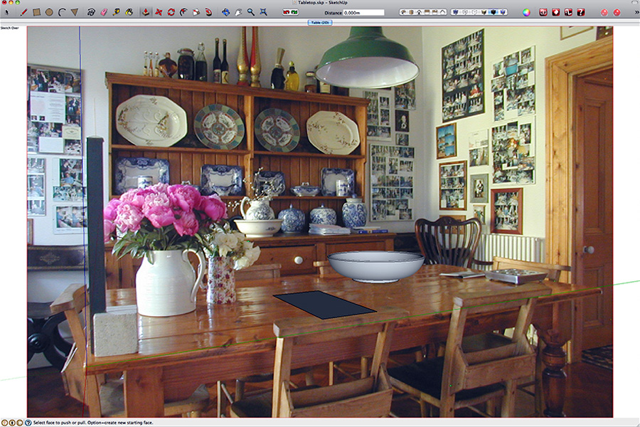
Step 15. Probably a good time to save again. Before we get into exporting we will model one more item. With the Rectangle tool draw a rectangle as shown here. Don’t worry that it is extending over the back of the chair a bit, we will move it behind in Photoshop later.
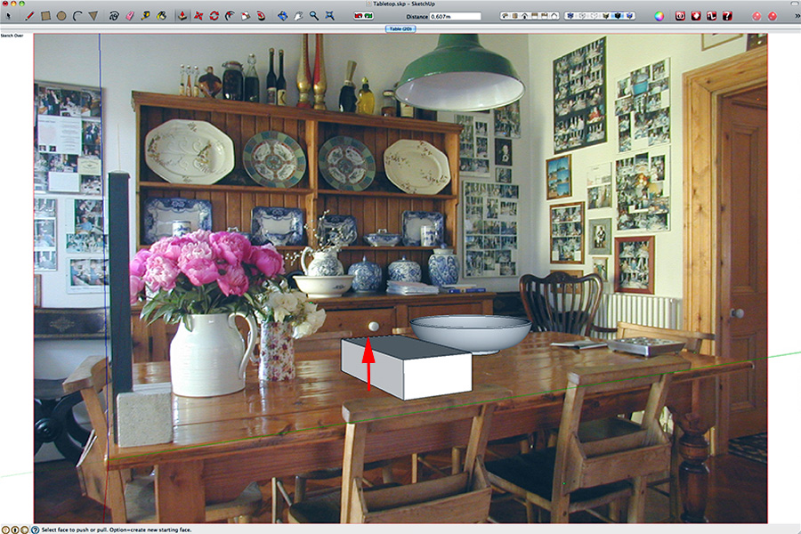
Step 16. With the the PushPull tool, extend the rectangle upwards into a 3D shape.
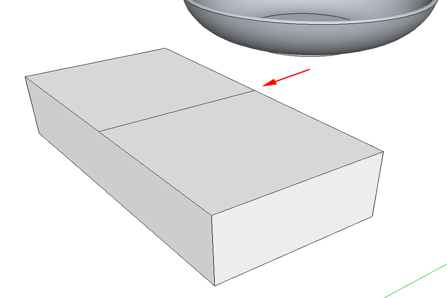
Step 17. Zoom in on the box and draw a line with the Line tool from the center of one side to the center of the other following the green axis.
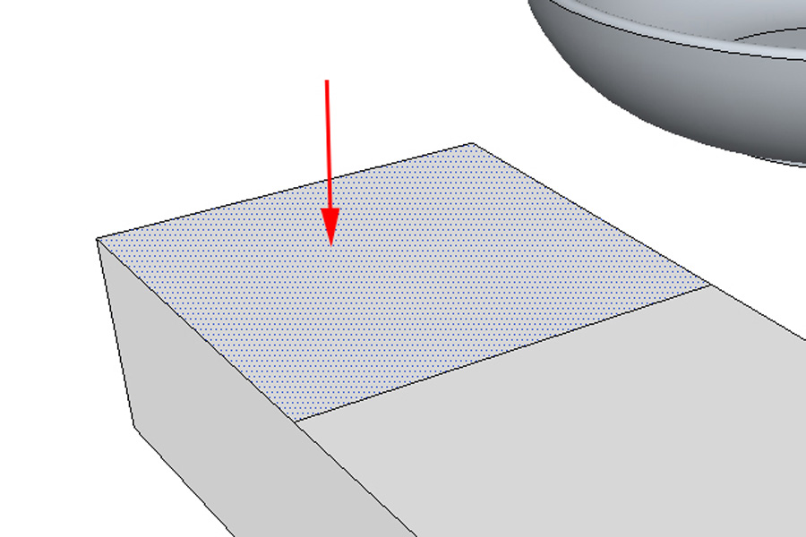
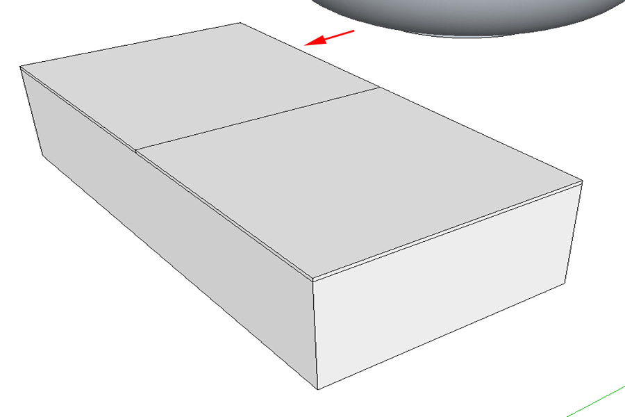
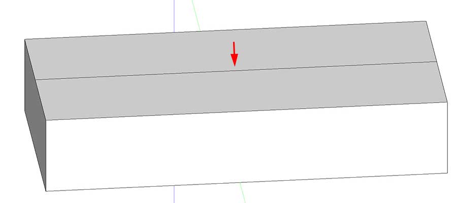
Step 18. To avoid ‘stickiness’ problems later we are going to do some grouping. Select the far top face with the select tool. (No need to bother about the edges.) and Edit > Make Group.
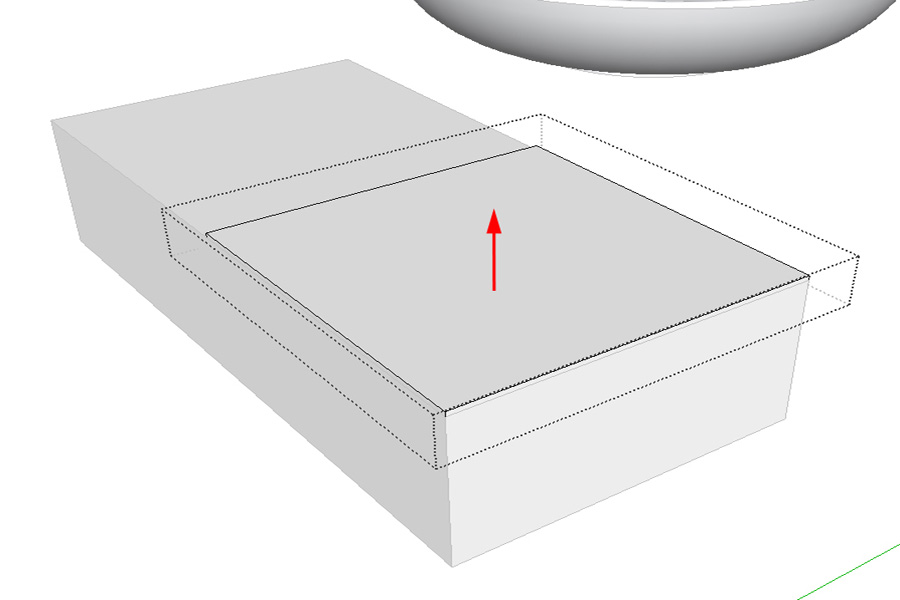
Step 18. Now repeat exactly the same thing for the near top face. With the near face still selected go to Edit > Group (1 in Model) > Edit Group. With the PushPull tool drag the top face up by just a tiny amount.
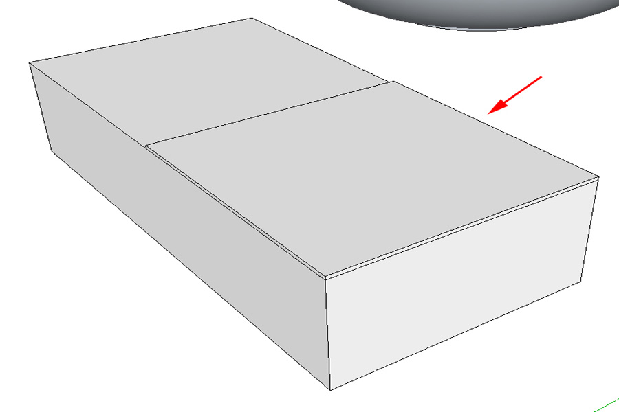
Step 19. Exit the group edit mode Edit > Close Group/Component.
Step 20. Now repeat exactly the same procedure for the rear top face. (Hint: When you drag the face upwards, drag up a bit too far, then move the cursor across to the top of the near face. The rear one will snap to the same height.) If you’ve followed along correctly, you should be looking at a box with its top two flaps closed.
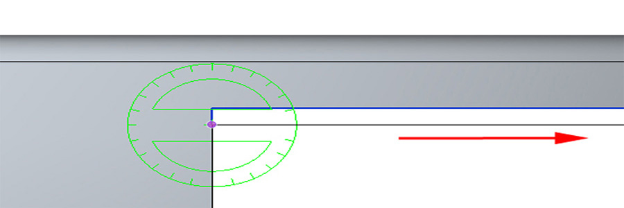
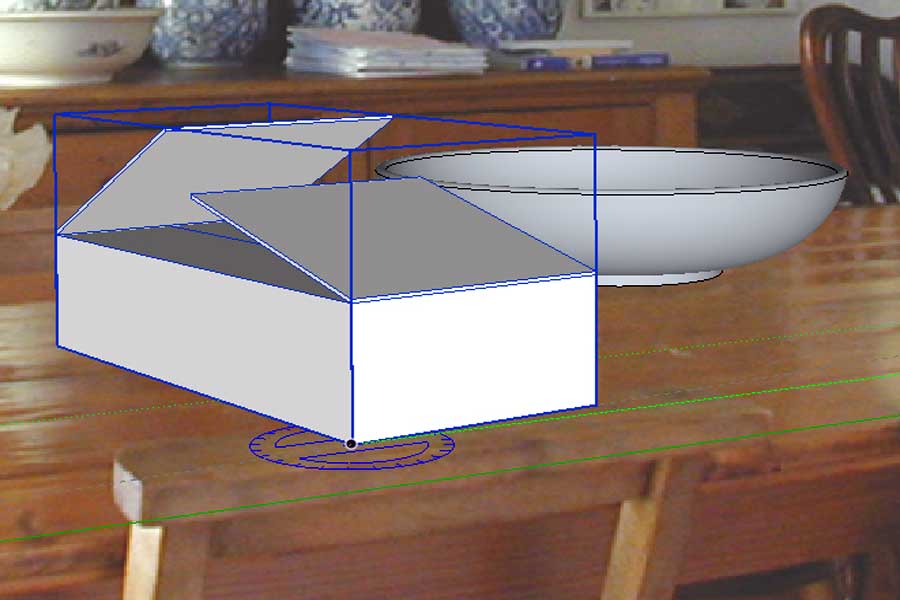
Step 21. Let’s open them a bit. Camera > Standard Views > Front and Camera > Parallel Projection. Zoom in onto the left flap. Select the rotate tool and move over the bottom left corner of the flap. Make sure the flap and not the box is showing the blue selection line and that the protractor is green.
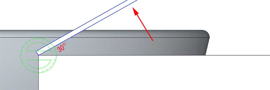
Step 22. Click once on the corner. Drag the cursor to the right along the bottom edge of the flap. Click again and drag upwards to open the flap about 30° (Two steps on the protractor).
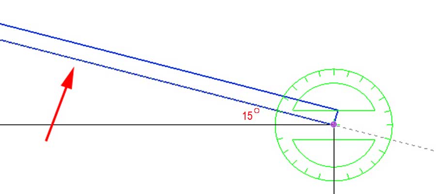
Step 23. Use the Hand Tool to slide the box over to the left and repeat the same thing for the right hand flap but this time about 15° (One step on the protractor).
Step 24. Zoom out so you can see both flaps. Select them both. Hide them Edit > Hide. With the Orbit tool tilt the box towards you so you can see inside a bit. Use the Line tool to draw a line from the center top left side to center top right side keeping on the red axis. Now we have the two closed inner flaps.
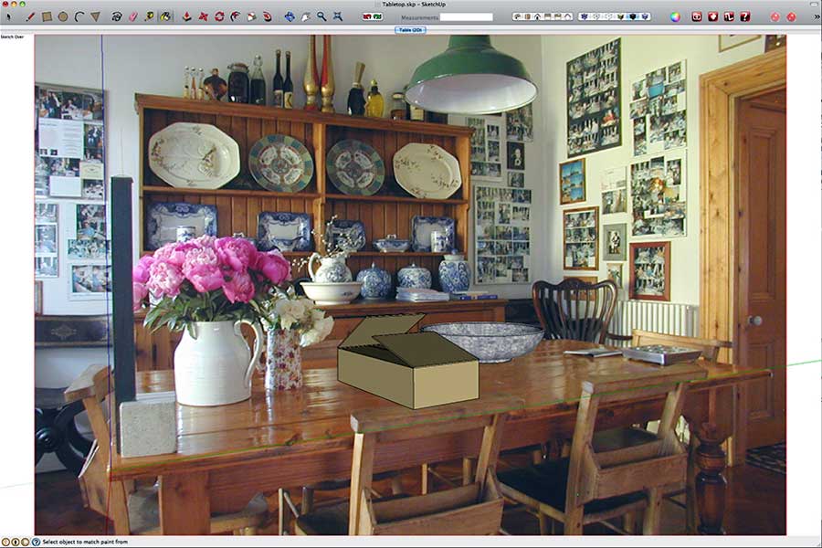
Step 25. Lastly unhide the open flaps. Edit > Unhide > Last. Marquee select the entire box and and Edit > Make Group. OK, Let’s look at this in the context of the photo. Click the Table 2D Scene button at the top of the window, Et voilà ! (as we say here in Belgium). Now we are getting there.
Step 26. Before we export I want to make a couple of tweaks to my models, and this time I want to do them in the context of my photograph. It would be nicer if the box was not aligned fair and square with table. Let’s rotate it a bit. Select the Rotate tool and move it over the box. Because of the sloping flaps the protractor will leap all over the place. We run the risk of rotating in some unwanted plane. To avoid this move the cursor clear of the box to its left till it turns blue – the plane of rotation we want. Holding down the Shift key will lock it onto this plane. So, holding Shift, slide the cursor under the box and snap it onto the near left corner. Click once and drag the cursor along the bottom of the box on the green axis and carry on almost to the edge of the window. We want to make a quite a small adjustment to the box and longer we drag out this line the easier it will be to control the rotation. Click again and move the cursor upwards to make just enough rotation to the box a more casual less ‘placed’ look.
Step 27. Before we start to finish up and export this is probably not a bad time to save again. If you want to play a little, try moving your models around on the red and green axes. See how once again they move perfectly in the context of the table top? (Moving them on the blue axis will lift them up vertically off the table top.) Once you have finished restore the file you just saved to put them back in their proper positions. Now it’s texture time. Select the Paint Bucket tool. For the box simply select a plain brown cardboard colour.
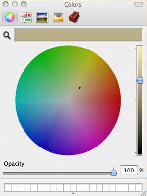
Step 27 (Mac view)
Step 28. Click in the box. Because we have grouped it the entire box will colour with a single click. No need to go chasing faces. Go to Materials in the Colour Picker, select Stone and use something like Stone Vein Grey to fill the bowl.
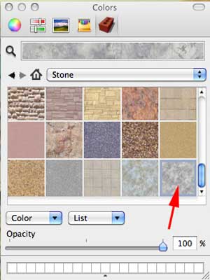
Step 28 (Mac view)
Here’s mine.
EXPORTING THE MATCHED MODEL IN 2D WITH AN ALPHA MASK
If we were an architect placing a design for a building into a photograph of its intended location we might well want to export as an unashamed drawing using our preferred SketchUp style, or perhaps as a ‘clay model’ with overlaid line details, or perhaps as a monochrome outline sketch. If we are a designer placing a new sofa in a photo of someone’s living room me might want to go a for more real textured look. All of these we can do with a SketchUp 2D export and some simple Photoshop post production. In fact with a little work and Photoshop expertise we can produce close to photo reality. Clearly, however, there comes a point where this becomes counter productive in terms of time against exporting to a full external 3D render application. But this also implies investment of both finance, study and time in another software. If you are a designer, artist, or architect the odds are you already possess some basic Photoshop skills and a simple 2D export with some Photoshop post production work may serve you better. So I shall be looking at two kinds of export. To complete this tutorial we shall export our models as sketches, just as they are now, with no further changes and no lighting settings applied.
If you have done Tutorial 1 then you will know the basics of exporting and creating an alpha mask for the export. However for this image we need to get deeper into this subject than was covered in Tutorial 1.
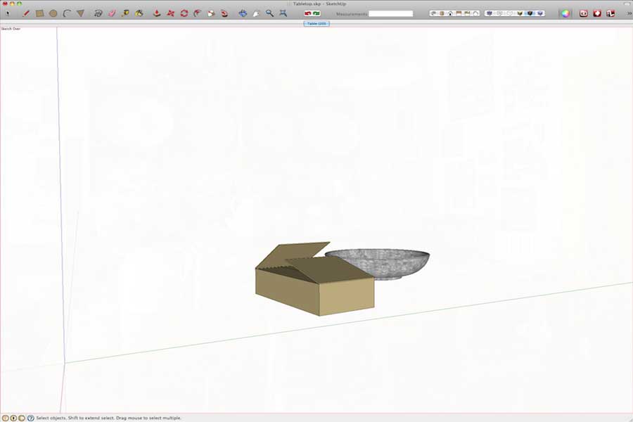
Step 29. We need to calculate the size we want SketchUp to export at so as to match the photo we are going to composite with our model. The first thing you need to understand is that, in 2D, Sketchup exports the entire modeling window regardless of the size of the model, or size of the photograph. It exports the window exactly as you see it on screen. In the case of my screenshot above, it will export the white empty spaces on either side of the image as well as the image itself. So the first step is to make the modeling window correspond exactly with the photograph. Drag and size your modeling window so you can see the whole window on on your screen clear of any dialogues overlaying it. (The contents will resize with the window and always fit one of the windows dimensions exactly.) Now shape the window so it just touches the red line around the photograph on all four sides. The size of your window is completely unimportant what matters here is that is that its shape is the same as the photograph. Once we are done we will have a photograph that exactly fills the modeling window. The next thing we need to know is the size of the photograph we are exporting to. Well in this case, to keep life simple, I made the photograph a nice clean round number – 1200 x 800 pixels. Since the photograph now exactly fits the modeling window, and SketchUp exports the entire contents of the window, all we need to do is to export at the size of our photograph. (If you are exporting to a large photograph there some rather arbitrary limits on the size that you can export from SketchUp in 2D depending on memory and operating system. To find out more about this refer to the footnote at the end of this tutorial.) We want to export only the models not the photo backing so we need to get rid of it. Open the Match Photo dialogue again. Window > Match Photo. Slide the Opacity slider all the way to the left and close the dialogue again. Now we have just our models on a white background.
Step 30. At this point I am going to ask Mac users to perform some steps that aren’t strictly necessary for them but they will help you understand the processes involved and you can work out for yourself afterwards how to simplify your life. File > Export > 2D Graphic. From the drop down box select PNG as file format. Open the Options dialogue.
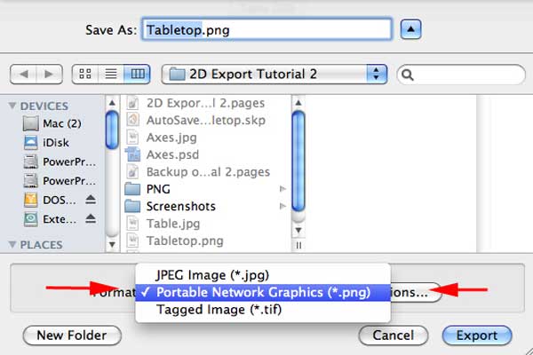
Step 30 (Mac view)
Step 31. Uncheck Use View Size, Set Width 1200, Height 800. Since we are specifying our dimensions in pixels anyway the DPI setting is irrelevant just leave it wherever it is. Check Anti Alias. If you are a Mac user you will be offered Transparent Background, however tempting it may look, uncheck it. We are going create a separate alpha mask afterwards.
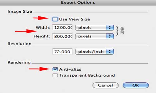
Step 31 (Mac view)
Click OK and Export using the default file name of TableTop.png.
EXPORTING AN ALPHA MASK OF JUST YOUR MODEL
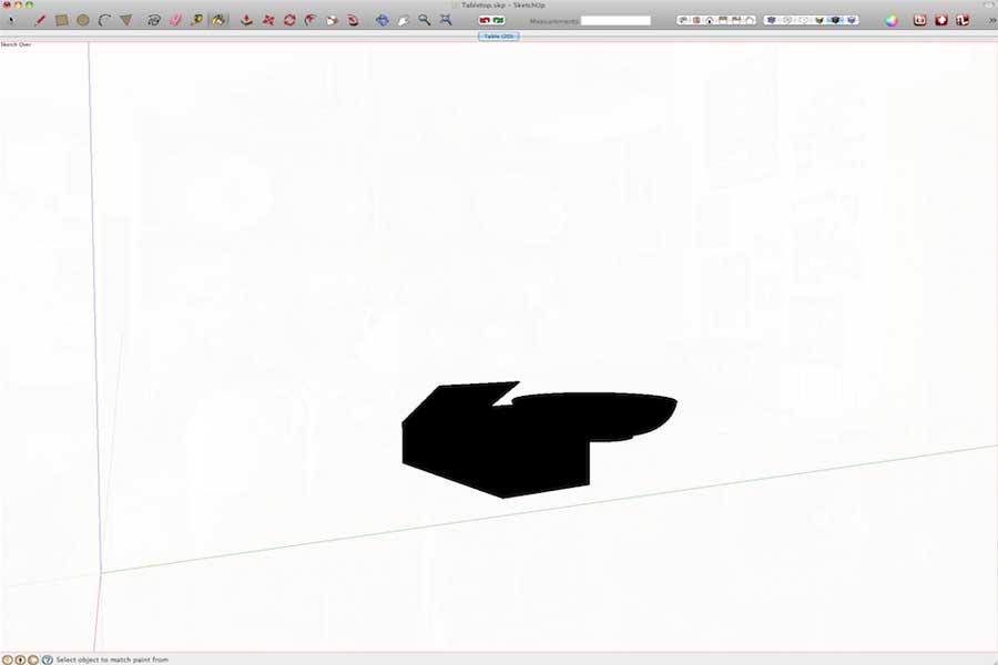
Step 32. We have already covered this in Tutorial 1. So just bare bones here. Open the Materials dialogue. Window > Materials. Select a solid 100% black and click in both models with the Paint Pot tool.
This our alpha mask. Export it with exactly the same settings as you did the models. Use the filename TableTopMask.png. (WARNING: The Options settings are not always sticky. Sometimes SketchUp remembers them sometimes it doesn’t. I don’t know what governs this …… full moon perhaps? Whatever, do check size before each export). That’s it for SketchUp….time to open Photoshop.
MASKING THE MODEL AND CREATING THE FINAL COMPOSITE
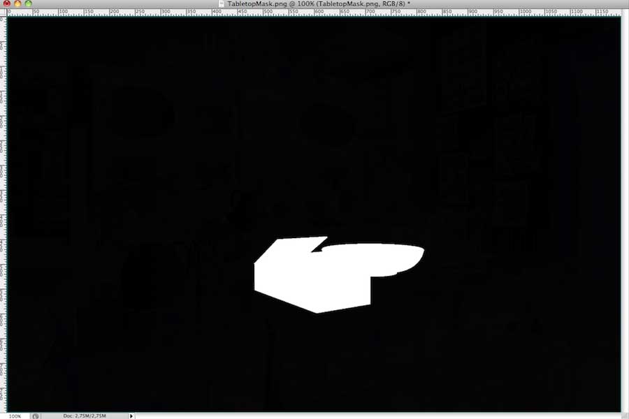
Step 33. Although the screen shots here are CS4, I have made the instructions, to the best of my belief, backwardly compatible to any version of CS, even though there may be better tools available in the newer versions. This not only covers a broader range of Photoshop users but is more likely to be easily adapted by users of other Photo editing software. Open both Tabletop.png and TabletopMask.png. Select the TableTopMask image and Image > Adjustments > Invert. This is your mask.
Step 34. Select > All and Edit > Copy. Switch to the TableTop image and add an empty layer mask. Layer > Layer Mask > Reveal All. Alt click in the Layer Mask icon in the Layers palette.
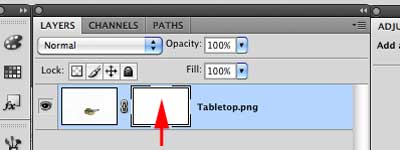
Step 34
Step 35. The image will turn white. We are now directly editing the layer mask itself. Edit > Paste the mask you cut from the TabletopMask image. In the Layers palette click in the image icon to restore the image.
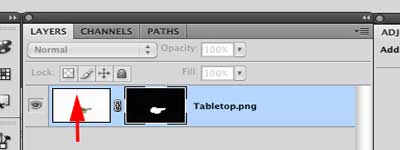
Step 35
Your model image is now surrounded by transparency. (NOTE FOR NON PHOTOSHOP USERS. Although the specific instructions will be different, the basis of this technique should work for any bit map editor that supports layer masks. If this is not the case an alternative method would be to create an empty Alpha channel and paste the mask image into it and then load the channel as a selection.)
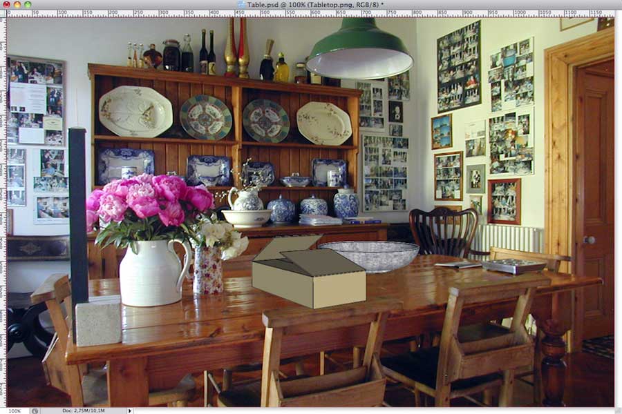
Step 36. Close TabletopMask.png and Open Table.jpg Position the TableTop.png and Table.jpg images so can see part of each of them. Select TableTop.png and holding down the shift key drag the layer from the Layers palette into the Table.jpg image. This will ensure that the new image layer with the masked SketchUp models is correctly placed in the Table.jpg image.
Step 37. Almost done. We can close the TableTop.png image now. Zoom in onto the back of the chair that is under the box. Click in the eye icon in the Layers palette to hide the box layer. With the polygonal lasso tool trace around the edge of the top of the chair back.
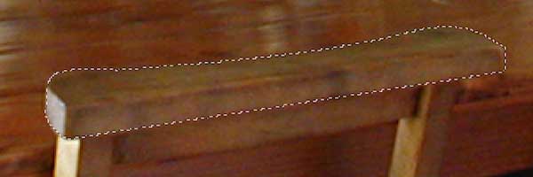
Step 37
Step 38. Enter Quick Mask mode and Filter > Blur > Gaussian Blur. Set Radius 1 pixel. OK. Exit Quick Mask mode.
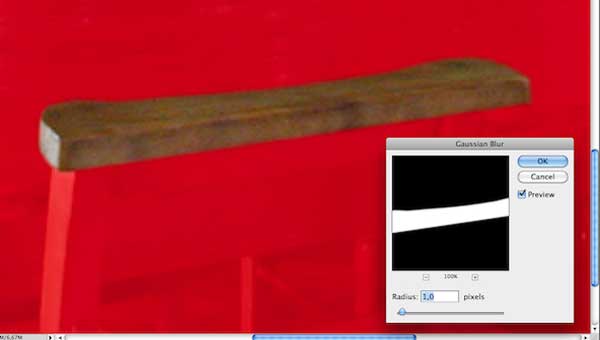
Step 38
Step 39. Click in the eye icon in the Layers palette again to turn the box layer back on. Click in the mask icon to select the mask.
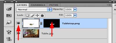
Step 39
Step 40. Edit > Fill. Use Black.
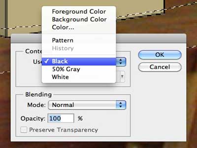
Step 40
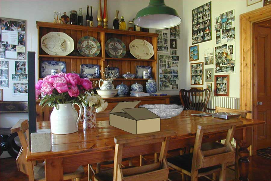
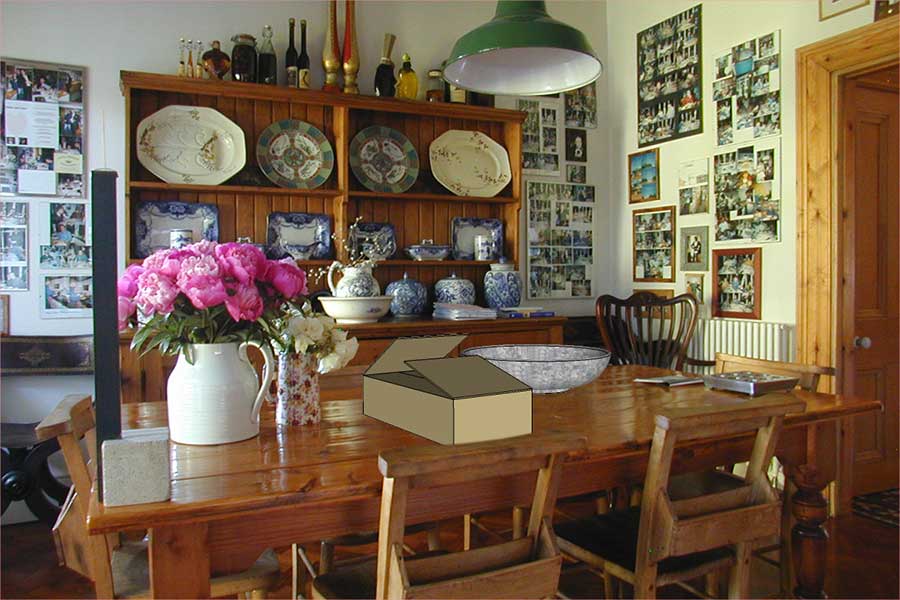
Step 41. Select > Deselect. Zoom out full image. The box is now behind the chair back. Save the image as a PSD with the name of your choice.
In Tutorial 3 we will look at ways, in both SketchUp and Photoshop, to create a seamless much more realistic blend of models and image. I hope you enjoyed this tutorial and look forward to sharing my next with you.
David
David Macdonald © February 2010








Hi David,
both tutorials are great! Have you done the 3rd one yet and if so could you send me the link?
Ta,
Sascha
I found this tutorial very useful, thank you very much.
but i am having a problem with my model going transparent when i click the 2D button at the top of the screen, the models zoom into place but are just outlines.
Please help
Ben.
Fantastic David
Nice tuto David!
I am pretty happy with this utility. I am loving to work exporting layers from sketchup to Photoshop in fact. But now would like to export the camera that i have created with the photomatch as a 3ds, so i could make some renders in 3ds max. Usually when you export a scene from Sketch Up as a 3ds the camera information can be added, so you can open the same exact scene in max. But it doesn´t seem to happen with the photo match. It actually exports a camera but although the point of view is similar, the FOV, lens, etc…have changed remarkably. I guess this info is lost because of 2d corrections with Photomatch or something like that, so my question is; Is it possible to get a scene with the camera we get after corrections with Photomatch?
Is it possible to make this photo match scenes (2d) actually 3d? Maybe convert them to normal scenes while keeping the camera corrections?
This is awesome… but DAvid, I have a problem – my style is “shaded with texture” and I’ve applied materials on the items but the materials don’t show up! They only show when I move my scene/camera (orbit). Can you give me some feedback to what I’m doing wrong?! Thank
mm i can understand little better please give me a video about this .
Hi David,
these tutorials are really great and easy to follow. is there any chance of you doing the third one? thnx 🙂
I was having the exact same problem with my models being transparent unless I orbited away from the default view. It turns out that you have to go to Window>Styles>Edit and choose the blue ‘Modelling Settings’ box. Uncheck ‘Foreground Photo,’ and the bowl and box textures will work again. This is also where you change the background photo opacity setting for the export portion of the tutorial.
Thnx Matt for the work around 🙂
Thanks very much for this tutorial. Very helpful
Would have never known how to work with a jpeg like this and i would love to as it could work very well with layering landscaping design ideas over photos of proposed sites. However I am stuck on the extrusion process of the bowl and I dont know if this is something I am misunderstanding about your instructions or if it is in fact your instructions which may be misleading, not intentionally of course. My problem is when I go to select the face of the circle and then switch to the follow me tool and you say select anywhere on the profile we just drew? Nothing happens? also the helper on the side shows it as more of a click and drag action aloing an already drawn line, but this doesnt work for me either, What am I doing wrong? how can I share a screenshot of my practice drawing so you can see my possible dilemmas? I look forward to hearing from you soon.
Kind Regards
Michael
@ Michael
First highlight the circle ..then select Follow Me Tool..then click face of the profile you have drawn.
Too much information inserted in between all the useful parts making it a too long tutorial. Sometimes background info interferes with the message.
brilliant ! useful and simple ! Nice job.