Aligning the Sun in SketchUp Accurately

Brian Lockyear is a computational designer in Portland, Oregon, using and developing sustainable design tools for architecture. He has a PhD in Computer Science from the University of Washington, and a Master of Architecture degree from the University of Oregon. He has a passion for where, when and how the sun enters a space. As an artist, Brian’s primary medium has been printmaking. He used the SketchUp renderings of the Portland Gas & Coke and twelve west buildings to create a series of fine art prints. In this tutorial Brian takes us through the steps he uses to align the sun.
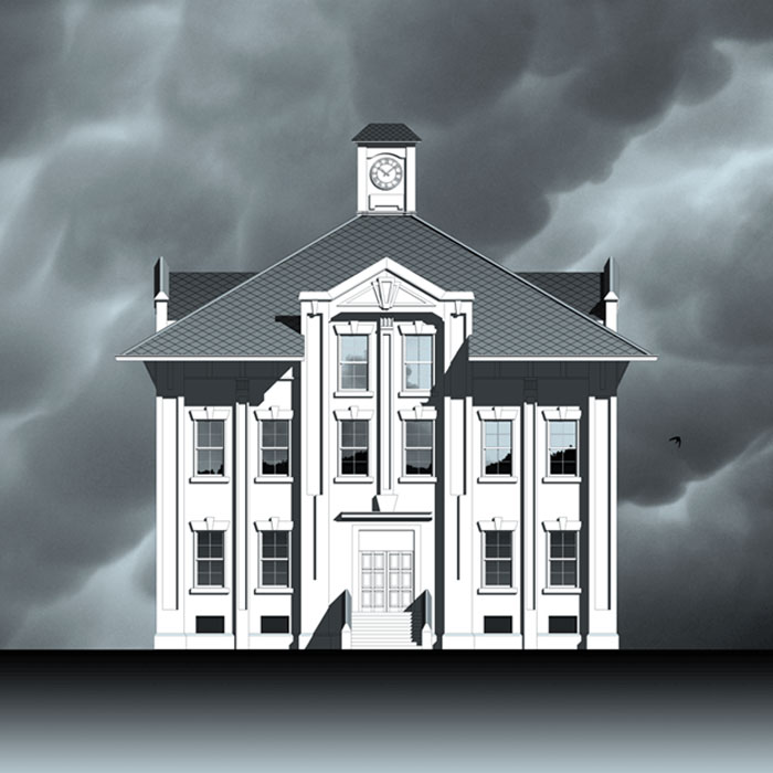
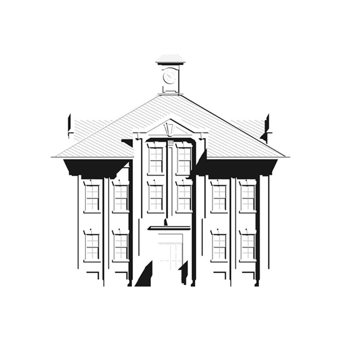
I admit it, I obsess about sun angles. It is my inner mathematician colliding with my inner architect. I love how traditional architectural elevations rendered in the Beaux Arts style provided shadows showing the depth and relief of the façade. This technique is particularly effective at showing-off historic buildings such as Portland’s 1913 Gas and Coke Company Building (Figure 2), however, it also works for modern, low relief buildings like Portland’s twelve west by ZGF Architects (Figure 3).
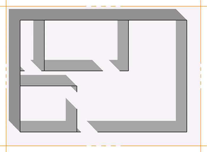
To develop these two images I used a parallel projection in SketchUp with my view aligned to the building’s front, and the shadows set to cast precisely from 45 degrees to the right and 45 degrees above the ground. With this classic orientation, a shadow that appears at 45 degrees on the building’s face now reflects an object’s edge protruding orthogonally from it. The length of the shadow gives a good indication of the size of the object as well. The same technique may also be used to give depth clues in section study as shown in Figure 4.
Direct rendering engines, such as the one built into SketchUp, are great for generating the clean crisp shadows required for these images. But it is difficult to find the right dates and times to position the sun at precisely the angles needed to cast the desired shadows. SketchUp does not provide for manipulation of the sun position directly as can be done in Rhino. (Kudos to them!) And while you can use the date and time sliders to move the sun’s position around until you get something that looks good, it is difficult to get it just right. Furthermore, once the sun’s position is adjusted for one elevation, how do you expose successive faces of the building for the others?
The solution is to use a technique from traditional drafting as described in C. Leslie Martin’s 1952 book, Architectural Graphics. In it, Martin illustrated the use of a simple cube-shaped “shadow box” to determine where shadows should be drawn. In SketchUp the object can be used to dial in exactly the location, date and time required to cast perfect aligned shadows.
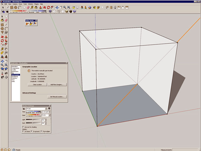
Creating the box in SketchUp is simple. Starting at the origin, extrude a cube of whatever size and units are easy to see in your model, say 10 x 10 x 10. Zoom in and rotate your view so that you are looking down and towards the positive X and Y axes. Next, shift and single click to select the three faces all adjacent to one another that you can see, which are the front, top and left faces of the box. Be careful to select only the faces and not their corresponding edges. Finally, delete the faces to leave only the back faces and the “crosshair” formed by the three bare edges. Turn on shadows under the View menu and in the Windows >Shadows popup window, enable the checkbox labeled “Display->From Edges.” At this point it is also helpful to select the remaining three back faces of the box and reverse their orientation using “right click >Reverse Faces.” This will reorient the faces towards you and improve their visibility. As shown in Figure 3, you are now looking into the interior of the box and the crosshair casts a shadow onto the receiving surfaces. You can also download an example shadow box here.
At this point we have a choice about how to proceed, depending on whether we’re working with a pro copy of SketchUp or not. If so, you will want to install the Solar North extension available as an add-on from the SketchUp Team. The Solar North tool allows you to change the north orientation of the model as well as to display the setting as an orange line on the base plane. You can now reorient your solar north angle as desired without rotating the model in order to get the correct shadows on each face in turn.
Unfortunately, the Solar North extension is not available without a pro license and orienting the model properly will require rotating it for each view. This is both clumsier and prone to introducing slight mathematical errors into your model as you orient to none-orthogonal directions. If you are forced to take that route, I recommend first saving a copy of your model so that you have an original version to return to after you are done reorienting.
First, set your model’s latitude and longitude to 45 and 0 degrees respectively using the “Set Manual Location” window under “Model Info->Geo-Location.” With north still at 0 degrees so that it is aligned to the positive Y-axis, adjust your date and time to solar noon on the Fall Equinox, 11:53AM on 9/21/2014, in order to align your shadows precisely along the north vector. Set the magic date and time by tweaking the values in the Shadows window. This is not perfect, but as close as we can get with minutes being the minimum time adjustment value.
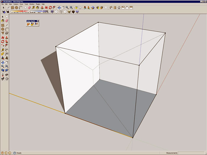
Figure 5: Initial construction of shadow box showing crosshairs & north angle 0. The orange line along the Y-axis marks north, visible when the Solar North extension is installed.
Next, rotate north by 45 degrees using the Solar North toolbar. The advantage of rotating the angle rather than the model is that SketchUp provides preset orthogonal views aligned to each axis. Assuming your model building has faces constructed orthogonally to those axes as well (A good idea for stable modeling), it is easy to expose each successive face of the building by switching to its view and setting north to the respective 45, 135, 225, and 315 degrees. As mentioned previously, rotating the model itself is hazardous as it can introduce tiny errors in point coordinates that will cause much grief later on.
With North rotated 45 degrees, the sun is now 45 degrees off the building face, and we need only adjust its elevation to get a vertical angle 45 degrees. Don’t touch that time and date! That’s what’s getting you right on the north vector. Instead, adjust your longitude under the “Model Info” dialog so that the shadow box crosshairs directly align with the lower back corner of the box. The magic latitude was 55.4 degrees N.
Now by changing your view to each successive building face, and the north angle to each respective quarter, you can quickly export beautifully stylized and consistent elevation studies. Separately exported images for lines, materials and shadows can then be recombined in Adobe Photoshop to further enhance the renderings as described in the excellent tutorial on masking by Lewis Wadsworth.
Thanks for reading.
Brian





[…] Aligning the Sun in SketchUp Accurately :: SketchUp 3D … – Aligning the Sun in SketchUp Accurately. Brian Lockyear is a computational designer in Portland, Oregon, using and developing sustainable design tools for architecture…. […]
Or search for the sketchup extension:
TIG: 45 Degree Shadows for Elevation v1.4
http://sketchucation.com/plugin/827-elev45shadows
Just at the finishing stages of designing my house only to discover that the sun project come from below the ground.
I must have started my design with the blue arrow down without noticing it.
Is there anyway to flip the sun about the horizon or flip either the house or the blue over so that the sun is above the horizon??
I do not have the PRO model (but love it).
Thanks for any advice you may have. – greg
@Greg Just group the whole model and use the rotate tool to rotate it 180 degrees. Should be OK then..